What is Control Relay?
Control relays have been an integral part of electrical devices for many years. However, with several advancements in electrical devices, the control relays have also undergone some changes. Nevertheless, a control relay is essentially an electromagnetic switch. Electrical relays or control relays are used to maintain the flow of electrical current through a conducting coil that opens or shuts the switch. A control relay also helps protect the circuit from power spikes. When a control relay has been integrated into the electrical system, there is no need to manually control the switch to change or isolate the state of the electrical current.
Advantages of Control Relay
Switching high power
Relays can handle high currents and voltages, making them suitable for switching high-power loads such as motors, lights, heaters, and other electrical devices. They enable control over devices that require more power than can be directly handled by low-power control circuits.
Electrical isolation
Relays provide electrical isolation between the control circuit and the load circuit. This isolation helps protect sensitive control circuits from potentially damaging high voltages, currents, or electrical noise present in the load circuit. It also enhances safety by preventing direct contact with high-power circuits.
Signal amplification
Relays can amplify weak control signals, enabling the control of high-power devices with low-power control signals. This amplification capability allows for greater flexibility in designing control systems.
Circuit protection
Relays can act as a protective mechanism by providing protection against overcurrent, overvoltage, and short circuits. They can help prevent damage to the control circuitry by interrupting the power supply when abnormal conditions are detected.
-

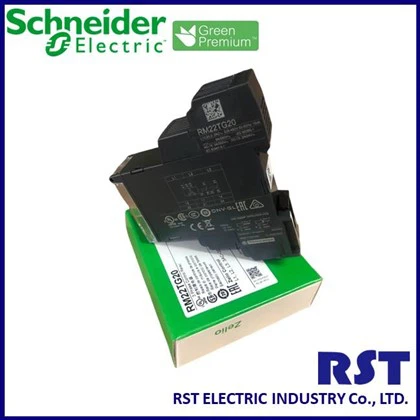
Schneider 3-phase Control Relay RM22TG20
Place of Origin: Indonesia. Brand Name: Schneider. Model Number: RM22TG20. Theory: Control Relay Add to Inquiry -
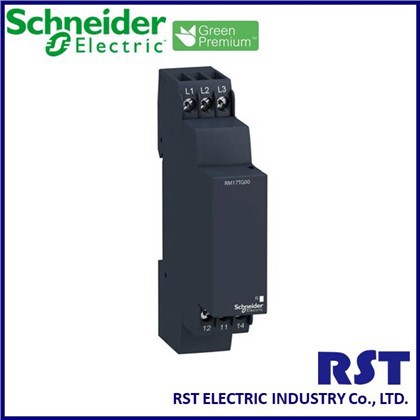
Schneider 3-phase Control Relay RM17TG00
Place of Origin: Indonesia. Brand Name: Schneider. Model Number: RM17TG00. Theory: Control Relay Add to Inquiry -
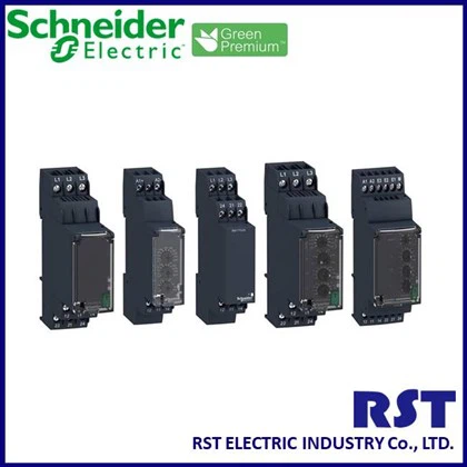
Schneider 3-phase Control Relay RM17TG20
Place of Origin: Aceh, Indonesia. Brand Name: Schneider. Model Number: RM17TG20. Theory: Control relay Add to Inquiry -
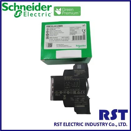
Schneider Current Control Relay RM35JA32MR
Place of Origin: Aceh, Indonesia. Brand Name: Schneider. Model Number: RM17UBE15~RM35JA32MR. Theory: Control relay Add to Inquiry -
Schneider 4-phase Control Relay RM35UB330
Place of Origin: Indonesia. Brand Name: Schneider. Model Number: RM35UB330. Theory: Control Relay Add to Inquiry
Why Choose Us
Experienced
With 30 years' experience, RST has dedicated to provide total solution of Industrial Facilities, Business or Residential Buildings distributing energy saving, providing customers complete after sales consultation of one stop shopping, national operation and local service.
Quality
Our team takes great pride in delivering high-quality products and services to our clients. We strive to exceed expectations and always put our customers first. With electrical power resources as the core of development, we offer total solution to our clients, becoming their trustworthy partners.
Wide selection
We service and sell all major manufacturers so you aren't limited to any one brand, make or model. We are a main distributor of Schneider products, Merlin Gerin products, Telemecanique products, RTR Capacitors, ETI Power Fuses, VEI LBS, AREVA LBS, Shihlin Electric products, Mitsubish products, Delta products, Mean Well products and Sunon AC/DC Fans.
24/7 availability
No matter the time of day or night you call, you'll get the same prompt, cheerful service.
Types of Control Relay
01/
Thermal overload relays
Thermal overload relays are crucial protective devices in electrical systems. These devices primarily prevent motors from overheating or potential damage from high currents. A thermal overload relay works on the principle of thermal sensing, which involves measuring the heat created by the motor during its performance. When the motor consumes an excessive amount of current for a prolonged time, notifying a possible overload, the relay trips and disconnects the motor’s power supply. Apart from protecting the motor and detecting potential danger to the electrical system, thermal overload relays also improve operational safety.
02/
Solid state relays
Solid state relays (ssrs) are made up of relay control systems that do not move. This relay requires a much lower control energy than the output power. It is under this circumstance that the power gained by this relay is much higher compared to other electromagnetic relays. Transformer-coupled ssr and photo-coupled ssr are the two types of solid-state relays that you can put in an electrical system.
03/
Magnetic latching relays
Magnetic latching relays utilise permanent magnets or components with high current absorbency to keep the armature in the same position as the coil is electrified after removing the power source. These relays comprise a thin metal strip that rotates between two edges. The switch is either connected or magnetised to one end of the little magnet. The opposite side is hooked to a little wire known as a solenoid.
04/
Lighting control relays
A lighting control relay is a protective device that is used to maintain the flow of current in all lighting systems for both commercial and residential uses. It comprises a switch that either opens or closes the current flows through the conducting coil. There can be an occurrence of excessive current passing through the lighting system which can cause potential electrical danger. With the help of lighting control relays, one can detect potential dangers and prevent them from happening while maintaining the performance of the lighting devices.
05/
Reed relays
Reed relays consist of two magnetic strips (reeds) sealed inside a glass tube. The reed functions as an armature and contact blade. The magnetic field provided to the coil is wrapped around this tube, forcing the reeds to move and, therefore, execute the switching function.
06/
Rectifier static relays
These relays have become popular due to the advancements in semiconductor diodes. It includes two rectifier bridges and a movable coil, often known as a polarised movable iron relay. The most common kind is relay substitutes, which are reliant on rectifier bridges and can be organised as phase or amplitude comparators.

Working Principle of Control Relay
The main principle on which an control relay function is that of electromagnetic induction. When current passes through the electromagnet, a magnetic field is created around it. There is the use of a switch for applying direct current (dc) to the load. When there is the application of direct current (dc) in the coil, it attracts contact. This is known as energizing the relay. And when there is the removal of the supply, the relay reaches back to its original position. This is called the de-energizing of the relay.
Interestingly, there are relays, where the control relay are initially closed. The circuit only opens when there is an electrical supply.
Control relay relays come with sensing elements for detecting the input voltage and switching the output with the use of a technique called opto-coupling.
How to Choose Control Relay
Electrical load considerations
Consider voltage, current draw, and switching capacity of loads the relays will control. Standard control relays operate from 5 to 240v ac/dc and switch up to 15 amp residential loads or 6 amp inductive. For heavier industrial loads, contactors can handle up to 600v and 200a.
Use narrow voltage bands for ac relays to prevent hum and chatter. Check motor start surge currents fall within relay specs if directly switching inductive loads. And allow a safety margin below published contact ratings – 20-30% for resistive loads, 50% for motors.
Mechanical design factors
Consider the mechanical life expectancy of relays in continuous switching applications like conveyor belts or pumps. Standard life expectancies range from 100,000-500,000 cycles. But more durable 10-20 million cycle relay contacts suit highly repetitive automation tasks.
Also, ensure good coil suppression to prevent back emf spikes from inductive loads damaging switch contacts. Look for varistor, capacitor, or zener diode suppression across coils for reliable performance.
Thermal environment
Determine the ambient operating temperatures relays will experience and verify rated coil insulation classes. Though industrial control panels see fairly stable temps, areas like steel mills and hvac plants span a wide range. High density panel designs also require vigilant heat dissipation planning with adequate relay spacing.
Interface modules
Many relays feature standard “ice cube” pin layouts, but others utilize unique wiring interfaces. For sensor compatibility, snap-on socket adapter modules convert disparate connections to uniform plugs, allowing interchangeable relay models. These modules also simplify replacement.
How To Wire a Control Relay?
Common relay terminal configurations
The most widespread relay terminal structure features a 5-pin inline layout. Two pins connect to the triggering coil, while the other three connect to individual switch contacts – normally open (no), normally closed (nc), and common. Inside, the coil actuates the contact armature when energized.
4-pin relays simply omit the normally closed terminal, while the no and common pins remain. This compact format works for simpler on/off load control instead of maintaining separate offline circuits. But the operating principle stays identical.
Step-by-step wiring instructions
Here’s a brief step-by-step guide on how to wire a control relay.
Determine relay type and contacts
First, confirm whether you need a single-pole, single-throw (spst) or single-pole, double-throw (spdt) relay. This determines available contact terminals. Also, decide if the load should stay normally open or normally closed when the relay coil is de-energized per your control scheme. This ensures proper operation when triggered.
Choose wire gauge for amperage
Consult automotive amp charts to specify adequate power wire gauges and circuit protection for your accessory load’s current draw. Also, verify the relay contact rating exceeds the load amperage to prevent overheating failures. Properly sized wires and rating margins prevent issues.
Make load connections
Connect the load wires to the appropriate relay contacts – either normally open or normally closed terminals. Use quality connection practices like wire crimping, insulation stripping, ferrules in screw terminals, and torque specifications to avoid loose wires or shorts. Protect wires with fused circuits.
Ground wires properly
Attach relay ground wires either directly to the battery negative terminal or grounded chassis points like screw heads. This prevents erratic behavior from noise in sensitive circuits. But ensure solid metal-to-metal contact.
Confirm secure fitments
Finally, validate tight wire crimps, torque specs, insulation clearance, and strain relief before energizing. The relay may plug into pre-wired sockets. But always double check workmanship for flawless operation.
Following basic relay wiring procedures and sound termination practices ensures reliable, trouble-free electrical control.
Precautions of Control Relay
Avoid a relay that makes and breaks both large loads and small loads. Because it is easy to produce contact spatters when switching on or off a large load, they will attach to the contacts of the small load on and off, leading to contact failure. If you have to use it in this way, please place the contacts that make and break the small load above the contacts that make and break the larger load during installation, but the reliability of the relay will be affected.
When the two sets of contacts are connected in parallel, the reliability of the connection can be improved, but the load capacity cannot be improved, because the two sets of contacts cannot be opened or closed at the same time.
Regarding the synchronization of the contact action and the ac load phase: When the relay contact action is synchronized with the alternating current phase of the switched load, if the contact is always turned on or off when the load voltage is high, it will cause the contact bonding or material transfer, which will lead to premature failure of the relay. When the relay is driven by a timer, a microcomputer, etc., the power phase synchronization phenomenon occurs.
When the relay is used at high temperature, its electrical durability will be lower than that at normal temperature, so please confirm it in actual use.
When there are multiple sets of contacts, please arrange the contacts on the same pole of the power supply as much as possible, and the load on the other pole of the power supply, so as to prevent the possibility of a short circuit due to the voltage difference between the contacts and the contacts.
Avoid short circuits between contact groups. Due to the miniaturization of electrical control equipment, the control components tend to be miniaturized. Therefore, when using relays with multiple sets of contacts, please pay attention to the type of load and the voltage difference of each set of contacts. Each set of contacts is recommended. It is best not to have an excessive voltage difference between them to avoid short circuits between contact groups.
In the relay contact circuit, when using a long wire longer than tens of meters, due to the presence of parasitic capacitance in the wire, an impulse current will be generated. Please connect a series resistance (about 10ω~50ω) to the contact circuit.
Precautions for electromagnetic relay contacts: When leaving the factory, the electromagnetic relays are all set to the reset state, but during transportation or when the relay is installed, it may become the action off state due to impacts, etc., so during construction use (power access time) set it to the necessary off state as required.
How to Maintenance Control Relay
Step-by-step guide to cleaning control relay
Cleaning control relay is a fundamental part of maintenance. Start by disconnecting the power supply to ensure safety. Open the relay housing to access the contacts. Use a contact cleaner or isopropyl alcohol on a cotton swab to gently clean the contacts. Avoid using abrasive materials that can scratch and damage the contacts. After cleaning, allow the contacts to dry completely before reassembling the relay and reconnecting the power. Regular cleaning helps remove any dirt, debris, or oxidation that can impede the relay’s performance, ensuring a reliable connection every time the relay operates.
How to test relay functionality periodically
Periodic testing of relay functionality is essential to ensure it operates correctly. Begin by checking the relay’s coil resistance using a multimeter. Compare the measured resistance with the manufacturer’s specifications. Next, test the relay’s switching operation by applying the rated voltage to the coil and verifying that the contacts open and close as expected. You can also use a test light or continuity tester to confirm the contacts’ functionality. Regular testing helps identify potential issues early, such as coil degradation or contact failure, allowing for timely repairs or replacements.
Identifying common signs of relay wear and tear
Relays exhibit several common signs of wear and tear that can indicate the need for maintenance or replacement. Look for visible signs of damage, such as burnt or corroded contacts, which can affect performance. Listen for unusual noises during operation, like buzzing or clicking, which can suggest internal issues. Check for inconsistent performance, such as the relay failing to switch on or off reliably. Regularly inspecting your relays for these signs helps catch problems early, preventing more serious failures and ensuring your system remains reliable and efficient.
Preventive measures to extend relay life
Taking preventive measures can significantly extend the life of your relays. Ensure relays are operating within their specified voltage and current ratings to prevent overloads. Maintain a stable operating environment, avoiding excessive heat and humidity that can accelerate wear. Use appropriate snubber circuits to protect against voltage spikes and transients. Regularly clean and inspect the relays to prevent dirt and oxidation from affecting their performance. Implementing these preventive measures reduces the likelihood of premature relay failure and helps maintain the overall health of your electrical systems.
Video
FAQ
As one of the most professional control relay suppliers, we warmly welcome you to buy original control relay in stock here from our factory. All our products are with high quality and competitive price. For more information, contact us now.
reverse power relay, thermistor relay, alexa smart relay